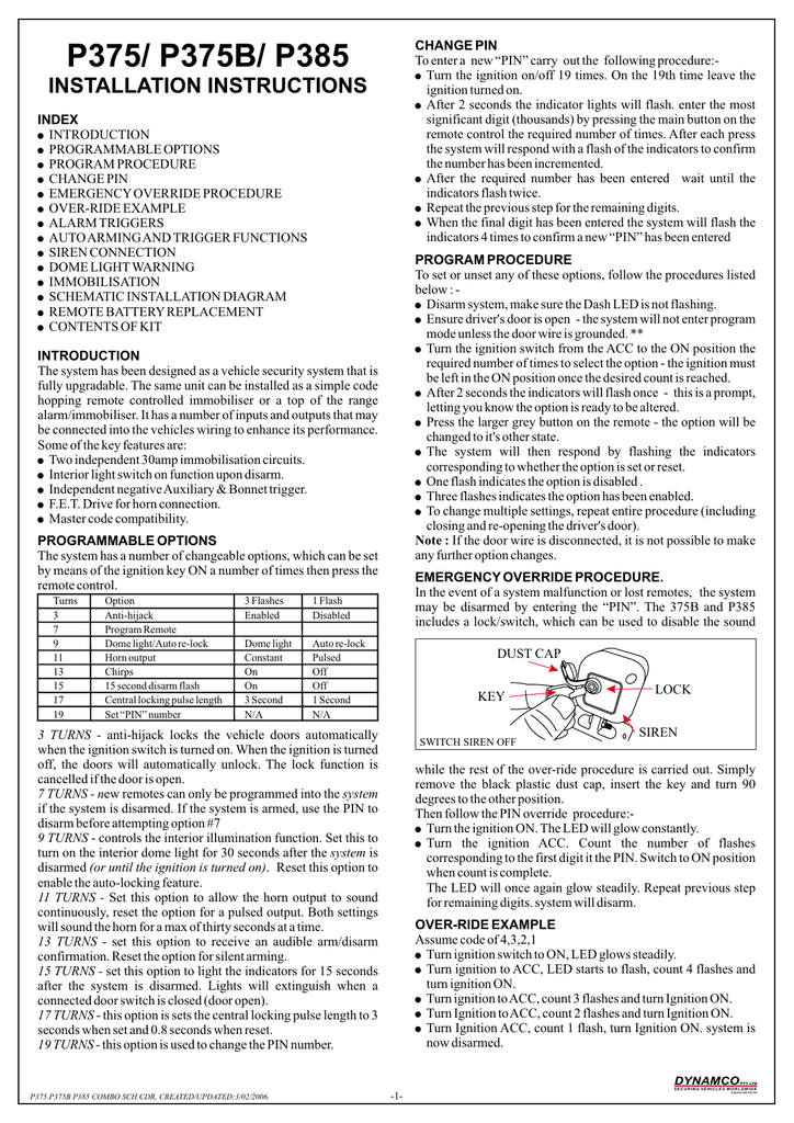
Each wire is marked with its function. It remove the connector from the back of the EIS module and bridge terminals 15r and terminal 30.
There is a wiring diagram which is not helpful.

Dynamco 6xr immobiliser wiring diagram. Alternaticly to disable the immobiliser for this unit you will need to grab from the wiring harness the WHITE and RED pairs has 2 immobilisers so there will be 4 wires of each colour. Is there any way of bye passing or disconnecting it. Wire connection guide immobiliser harness wiring diagram ___ ___ ___ ___ ___ ___ power harness wiring diagram ___ ___ ___ NOTE.
Immobiliser - Autowatch Ti I have purchased a autowatch Ti immobiliser. Dynamco Immobiliser Wiring Diagram Rel 003 Relay Switch. Dynamco Immobiliser Wiring Diagram wiring diagram is a simplified within acceptable limits pictorial representation of an electrical circuit.
PARA275 P275 CYCLOPS Remote Immobiliser. Posted by paul careswell on Nov 02 Want Answer 1. This is the where the key would be to allow the car radio to work but no engine function.
To name only a few of the improvements. Dynamco Immobiliser Wiring Diagram. Dynamco has upgraded the OE Upgrade higher current immobilisation and multiple plug-in sensors available.
Dynamco is a leading specialist in electronic vehicle security. IN many cases the manufacturers of the vehicles change wiring harness suppliers and. Immobiliser Procedure assuming your PIN is 24531 1.
Turn the ignition switch to the ON position. This is the Dynamco P165 vehicle immobiliser. Having tried the buttons new batteries resyncing the remote and the spare key fob.
Posted by Anonymous on Feb 23 2014. Wiring Diagram July 26 2019 2050. The system is operated by the vehicles original equipment remote and has Entry point protection of doors.
Etc its time to enter the EKA Emergency Key Access Code to bypas. Need wiring diagram for 4xr-5 dynamco immobiliser hi just want to know I have a 4xr-5 immobiliser on my hyundi exel and I think it not working cause I get no lights on dash when I turn the key and it use to work. 2 ENSURE ALARMIMMOBILISER CENTRAL LOCKING SIGNALS ARE SET TO SEC IN BN RE GY etc are all ACTUATOR 1CL CONNECTION DIAGRAM DIRECT MOTOR Wires name changes.
GND2 Ground 2 GND1 Ground 1 1 12V 2 3 NOTEAll wires are BLACK. However do this at your own risk. Generic wiring schematics seldom match the OEM wiring as to get the diagram the book publishers have to virtually strip down a vehicle as the diagrams are copy write protected.
Para205 P205 Cyclops Transponder Immobiliser. The system may provide keyless entry and visual confirmation via the vehicles indicators. Need wiring diagram for 4xr-5 dynamco immobiliser - Fixya.
The system is fully automated and thus the user doesnt have to arm or disarm. For general help or enquires regarding installation or technical information on any of our products please contact our helpdesk. This Australian Standards approved immobiliser provides two circuits of automatic engine immobilisation operated by rolling code random encrypted remote control.
Dynamco is a company passionate about its future and we are investing in growth by bringing our customers new and. Digit 1 Turn the ignition key to the ACC position. There is a wiring diagram which is not helpful.
Need wiring diagram for 4xr-5 dynamco immobiliser. I recommend getting a wiring diagram specific to your car to be sure of the terminals. Basically you then want to cross the wires over see the diagram below.
This area is for professional installers of Dynamco products only. Dynamco is one of the worlds leading specialist companies in electronic vehicle security designing and customising systems to combat the increasingly sophisticated professional car thief without compromising the user friendliness of the systems. 12 24 Volt Trolling Motor Wiring Diagram wiring diagram is a simplified within acceptable limits pictorial representation of an electrical circuitIt shows the components of the circuit as simplified shapes and the faculty and signal associates along with the devices.
BYPASS DYNAMCO IMMOBILISER - Cars Trucks. Nitrous outlet winmax wiring diagram Nitrous outlet wiring diagram Relay wiring diagram 3 wire fuel shut off solenoid wiring diagram Nitrous wiring diagram with purge Engine immobiliser wiring diagram Alarm immobiliser wiring diagram Car immobiliser wiring diagram 1kd-ftv wiring diagram 2kd ftv toyota 2kd ecu wiring diagram Toyota 2kd ecu wiring diagram pdf 1kd ecu wiring diagram. Immobiliser - Autowatch Ti I have purchased a autowatch Ti immobiliser.
Please remove all wire description tags from wiring after connection to the vehicle. It shows the components of the circuit as simplified shapes and the skill and signal contacts with the. This position is where the key remains while the engine is running.
This Australian Standards approved immobiliser provides two circuits of automatic engine immobilisation operated by an electronically coded transponder with a dash mounted high intensity red LED. It was manufactured in Australia in Perth by Dynamco and is a reliable and trouble-free immobiliser. I need to know which wires the circuit 1.
AUX becomes CDL SENSE. The description listed. This Australian Standards Upgrade Alarm transforms an Original Equipment vehicle keyless entry system into an Australian Standards alarm system.
If you want to find the other picture or article about Dynamco Immobiliser Wiring Diagram.

Para275 P275 Cyclops Remote Immobiliser Product Dynamco

Car Security P275 Remote Immobiliser Cyclops Paralyser Dynamco 12v For Sale Online Ebay

Dynamco P165 Car Immobiliser Youtube

Does Anyone Have A Copy Of The Schematic Wiring Diagram For Fixya


Posting Komentar